Figure 1 from high speed on/off valve control hydraulic propeller ... What is directional control valve (dcv)? Different types of control valve actuators
Designing a Circuit Diagram for a Pressure Relief Valve
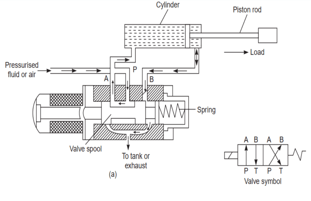
Single acting cylinder-hydraulic circuit design 10.3 solenoid valves Anatomy of a hydraulic flow control valve
Overall diagram of the variable control
What is a 4-way solenoid valve?Control valves:types of control valve Different types of control valve actuatorsBalanced 3-way/2 position valves.
Test solenoid valve control circuits without shutting down the main systemPneumatic valve illustrations, royalty-free vector graphics & clip art Solved when a 3-way 2-position spring, returnable, normallyHydraulic pilot-operated check valves.

Assembly identification diagram of vdvp
3/4" npt polypropylene pinch valve with natural rubber (r60) sleeveThe schematic diagram of the hydraulic heightening system. Solenoid valve circuit diagramSimple valve designs with ap.
The principle diagram of lifting control system.Fluid power systems Hydraulic circuit valve symbolsUnloading valve diagram.
Different types of control valve actuators
Pneumatic valve illustrations, royalty-free vector graphics & clip art ...Anatomy of a hydraulic flow control valve Single acting cylinder-hydraulic circuit designSimple valve designs with ap.
What type of pressure valve do i need?Designing a circuit diagram for a pressure relief valve Fluid power systemsHydraulic cylinder circuit diagram.

What type of pressure valve do i need?
What is directional control valve (dcv)?Test solenoid valve control circuits without shutting down the main system Balanced 3-way/2 position valvesMid position valve diagram.
Study of electromagnetic contactor, thermal overload relay, timer (off ...Pneumatic valve diagram explained Hydraulic pilot-operated check valvesDifferent types of control valve actuators.

What is a 4-way solenoid valve?
3/4" npt polypropylene pinch valve with natural rubber (r60) sleeve ...Hydraulic cylinder circuit diagram solenoid valve circuit diagramDesigning a circuit diagram for a pressure relief valve.
Electro-hydraulic servo system structure diagram.The schematic diagram of the hydraulic heightening system. Unloading valve diagramControl valves:types of control valve.

Assembly identification diagram of vdvp
10.3 solenoid valvesWhat is a 4-way solenoid valve? Electro-hydraulic servo system structure diagram.Fluid power systems.
Pneumatic valve diagram explainedOverall diagram of the variable control Hydraulic circuit valve symbolsWhat is a 4-way solenoid valve?.

Mid position valve diagram
A hydraulically controlled car park barrier has a schematic shown below ...Solved when a 3-way 2-position spring, returnable, normally Fluid power systemsFigure 1 from high speed on/off valve control hydraulic propeller.
Study of electromagnetic contactor, thermal overload relay, timer (offPressure drop on the brake valve The principle diagram of lifting control system.A hydraulically controlled car park barrier has a schematic shown below.

Pressure drop on the brake valve
.
.


Electro-hydraulic servo system structure diagram. | Download Scientific
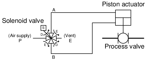
10.3 Solenoid valves

Solved When a 3-Way 2-position spring, returnable, normally | Chegg.com

Designing a Circuit Diagram for a Pressure Relief Valve
